Difference between revisions of "ETEC Autoscan"
| (2 intermediate revisions by the same user not shown) | |||
| Line 270: | Line 270: | ||
This is the Stock Magnification controll of the Autoscan, which requires the user to compute the system magnification themselfs. | This is the Stock Magnification controll of the Autoscan, which requires the user to compute the system magnification themselfs. | ||
| + | ==== Digital Magnafication Unit ==== | ||
| + | The small coax connectors used on the rear of this unit are the [https://w140.com/tekwiki/wiki/BSM_connector| BSM connector] also sometimes called MB connector. | ||
| + | |||
| + | [[Category:ETEC]] | ||
| + | [[Category:Pages with broken file links]] | ||
== Promotional Material == | == Promotional Material == | ||
| Line 279: | Line 284: | ||
[[Category:ETEC]] | [[Category:ETEC]] | ||
| + | [[Category:Pages with broken file links]] | ||
Latest revision as of 15:25, 15 February 2024
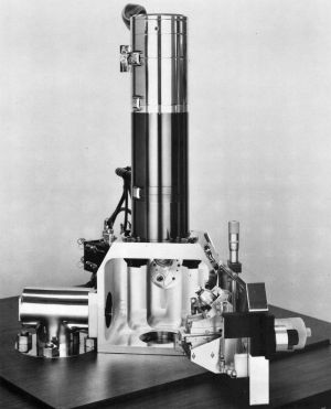
The ETEC Autoscan is a Scanning Electron Microscope developed by the ETEC Corporation in 1972.
in order to get PDF images to work add "-sstdout=/dev/null", to pdfhandler.php in the fallowing structure:
"-dBATCH",
           "-dNOPAUSE",
           "-sstdout=/dev/null",
           "-q",
           $srcPath
Overview
The Autoscan was avalible in 2 main configurations, one with a combined Console and Column, and one with Split Console and Column, the latter being the more high end version.
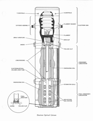
The column its self consists of 2 Iron clad Solenoids, with the top forming 3 lenses used as the condensor Lens, and the lower forming, with the aid of polpieces, the objective lens. 2 basic Objective Lens configurations where avalible, the more basic having a single, prealigned Aperture housed at the top of the Column Liner tube, and the other having a centerable Aperture stick with 4 positions for 2mm diameter aperatures. Both lenses are of equal dimension, and run off the same power supply.
Nested within the solenoid casing of the Objective lens, lies the defelction and Stigmation unit, which is a Resin cast cylinder containing the 2 sets of deflection coils, as well as the dual Quadropol Stigmator for the objective lens. There existed 2 upgrade options for this assembly, one adding beam blanking, the other allowing indevidual control of the scan coil sets, in order to produce Psudo Kikuchi Lines in conjunction with the Aperture stick Objective lens.
In North America, the Autoscan was distributed under the name ETEC where as it was distributed under the Siemens name for the rest of the world.
Specifications
| Electrion Source | |
|---|---|
| Accelerator Type | Single Stage Electron Gun |
| Cathode Type | Tungsten Hairpin / LaB6 / Cold Field Emission |
| Accelerating Voltage | 1-30, 2.5, 5, 10, 20, 30, (50) KV |
| Stability | |
| Cathode Heating Methode | HF AC |
| Alignment Methode | X, Y, Mechanical |
| Condensor | |
| Number of Condensor Lenses | (1), 3 lens gaps |
| Current Stability | |
| Stigmator | Not present |
| Minimum Spot Size Diameter | N/A |
| Condensor Alignment | Not Present |
| Lens Type | Electromagnetic |
| Stage | |
| Holder Type | Swing Door / (Airlock Loading) |
| Special Holders | Freeze Holder, Airlock Cartridge, TSEM Holder, IC Holder |
| Sample Tilt Range | -5° to 45° (Large Specemin Goniometer), 0° to 90° (Small Specemin Goniometer) |
| X, Y Travel Range | ± 12.5 mm |
| Z Travel Range | 25 mm |
| Objective Lens | |
| Focal Length | |
| Adjustment Range | |
| Spherical Error | |
| Chromatic Error | |
| Current Stability | |
| Stigmator | Dual Quadropol, Electromagnetic |
| Alignment Aids | |
| Point Resolution | 10 Å, (7 Å) |
| Minimum Focal Length Variation | |
| Lens Type | Electromagnetic |
| View Screen | |
| Type | ZnS + CdS CRT |
| Size | 18 cm x 18 cm |
| Camera | |
| Lens Type | "Plate Film, Manual Feed / Rollfilm Side entry |
| Film Format(s) | 4x5" / 6x9 cm / 35mm |
| General | |
| Magnification (Steps) | N/A |
| Magnification Range | 5x to 240 000x / 20x to 500 000x |
| Magnification Gauge Type | Mechnical / LED 7 Segment Display |
| Image Distortion | |
| Image Rotation Compensation | NO |
| Specemin Chamber Pressure | 2e-5 Torr to 2e-6 Torr (cryopump) |
| Electrical | |
| Power Consumption | 2.5 KVA |
| Input Voltage | 115V / 230V AC |
| Frequency | 50 Hz or 60Hz |
| Cooling | |
| Water flow Requirment | 2 l/min |
| Water Pressure | 1.5 Bar |
| Inlet Temperature Range | 15°C to 24°C (20°C Optimal) |
| Acceptable Temperature Rise | |
| Mechanical | |
| Number of Sub Units | 1 (2) |
| Weight of Column | |
| Weight of Powersupply | |
| System Total Weight | 450 Kg |
Accesories
Many accesories and upgrade options for the Autoscan where avalible a most likely incomplete list of them fallows
Detectors
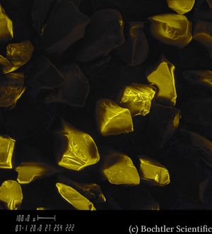
SE Detector
While Technically a standard part of the Autoscan Microscope, it is still listed for wholeness sake
Semiconductor BSE Detector V1
This detector consists of a semi circle of Silicon PIN Diodes covered with Aluminium, in order to shield them from light. These Diodes are mounted on an arm which is plugged into a 3.5mm TS jack mounted on a modified SE Detector. The preamplifier of this detector, much like that of the SE Detector sits within the cassing of the SE Detector, and its output is likewise routed through the same cable as the SE Signal. The video stream of this detector can not, in the normal configuration of the system, be used in conjunction with the TV Scan generator.
This detector sits extreamly close to the objective lower polpiece, and therefor has high detection efficiancy. The video signal from this unit proves difficult to work with, as the range of settings where it produces an aceptable video signal are very narrow. Over or undershoot from these settings will yield a blank image of either entirly white or black. It has been found by experiments, that the gain must be turned up to nearly the maximum the manual video maplifier will permit, while then using the offset (Brightness) control to yield a usuable image.
Experiments have also found this detector to be usable only up to and including 10Kx magnifaction, as indicated by the DMU, anything beyond that will yield only noise. The usuable working distance of this detector is between 10 mm and 35 mm. In order to yield images of good contrast, usually a fairly large variation of the Elemental Number is required.
Additionally, this detector requires longer intigration time them the SE Detector, owing to its high noise output, and low signal intensity. Typically settings of 2000 Lines, and a speed of 3 on the Analog Scan Generator, yield acceptable images.
Transmission Scanning Electron Detector
This detector is based on the stock SE Detector, with the differences in its construction beeing the lack of the 10KV type HN Connector, and the assosciated cage. In addition, the long bent lightpipe present on the SE Detector, is instead replaced by one of short length, only 1/4" above the flange. At the end of this lightpipe, the same Scintilator Disc as used in the SE Detector is mounted.
The Detector Assembly is mounted on a circlular flange below the main Chamber, when not in use, the scintilator is covered by an aluminium cap.
The Working principle of this detector is fairly simple, as it is simply a shadow projection transmission microscope, which uses scanning of the electron beam to produce an image.
This detector is usually used in conjuction with the TEM grid holder, which mounts in either the Large Specemin Goniometer, or the 90° Goniometer. For use, the stage is moved to nearly its extream, in order to open a slot within the stage, through which the electron beam can reach the transmission detector.
Power for the PhotoMultiplyer is either supplyed via the same PMT PSU (collector Controll) as the SE Detector, or alternativly by a seperate Collector Controll Modual. Power is supplied via a MHV terminated COAX Cable. The video signal is supplied much like that of the SE Detector, via a Circular Swagelock connector at the rear of the PMT housing.
Cathodo Luminescence Detector
Yet another detector based on the stock SE Detector, this unit mounts to one of the 2 primary Detector ports located at 45° to the left and right of the SE Detector. Much like the TSEM detector, this unit lacks the HN connector pressent on the SE Detectors rear.
Unlike both detectors, the light pipe of this unit, is exposed to the chamber, and bent in such a way, as to point at the specemin.
Again, the power for the PMT is supplied via a MHV Terminated Coax cable, which is either powered off the SE Detector PMT Power supply, or alternativly given its own Collector Controll. Its output signal is again present on the same Swagelock connector as that of the SE Detector.
Not much else is known about this detector at present, and it is now known if a production unit was ever released. The above information was gained from documentation from ETEC. (see below for more details)
Specemin Current Proscessor
This is one of the 2 variants of the Specemin Current measuring system avalible for the Autoscan. The proscessor unlike the Specimen Curent Meter, is a self contained unit plugging into the NIM bins, and beeing connected to the stage output via a Triaxial Connector. How this connector is terminated on the stage is unkown, as no installed unit has been seen by this author. On the unit within the collection of Lukas Bochtler the Specimen Current Proscessor is connected via a RG174 cable from the rear of the unit (rewired to use a DVM BNC connector) to the stage junction box.
The Specimen Current Proscessor is capable, much like the meter, to produce Specimen Current images. It is in the most basic sence a high speed Electrometer based on the Analog Devices 118A opamp.
Specimen Current Meter
This is the older version of the Specimen Current Processor, and consists of 2 parts. A Preamplifier which is connected to the auxilary port to the right of the Chamber, which houses the Electrometer, and a multipin Feedthrough, terminating in a 3.5mm TS jack within the chamber. As well as a NIM Module which contains the metering circuits and controls. Not much else is known about this unit, as this author has not seen the NIM Module.
The Electrometer is, unlike the Specimen Current Processor, connected to the stage via a 3.5mm TS connector, and also functions as the ground point for said stage. Newer stages where fitted with grounding systems incorperated within the stage feedthrough, and did not use the TS Plug. These stages can however be made compatible with the Specimen Current Meter via modifications to the grounding setup within the stage.
AutoSpec X-Ray Spectrometer
This exceedingly rare detector was a Crystal Diffraction Xray Spectrometer avalible for the Autoscan. It was mounted on a 45°, relative to the column, port on the right of the Specimen Chamber, and overhung the door and chamber by a considerable amount.
2 such units are known to have existed, both of which have unfortunetly been scrapped. Thus not much more information is known about this detector.
NIM Modules
2 Width Vacuum controll
This is the stock vacuum control for the Autoscan, unlike the 4 width unit, it lacks the ability to read the High vacuum of the Specemin chamber, relying solely on the Thermocouple gauge to determine if operating pressure has been reached within the Specimen chamber.
This control unit has automated valve controls to allow easy specemin exchange and operation of the instrument. However, much like the 4 Width unit, it too lacks the ability to automatically Startup and Shutdown the system. Instead requiring user intervention via manual override switches to do so. This aperent design flaw of the system is explained by the operating scheme of the Autoscan, as intended by ETEC where the units vacuum system (both diffusion pump and Roughing Pump) where to remain active at all times. Shutdown and Startup was only intended for servicing the unit, and not for normal day to day use.
The Vacuum Controller features status LED's indicating the state of the various Pneumatic and Solenoid valves within the Autoscan's vacuum system, as well as status LED's for the Diffusion Pump, Roughing Pump, Water Failure, and Air pressure Failure
4 Width Vacuum Control
This is the upgraded version of the aformentioned 2 width unit, which in addition to the above ameneties also adds a Penning Gauge for the Specimen Chamber. The asocieated gauge head is manufactured, like the Thermocouple gauges, by the Varian Corperation, and works on the principle of the cold cathode ion gauge as described by Penning.
This unit also features more gauges, and in the case of the unit installed on the Autoscan owned by Lukas Bochtler, also adds controls for the airlock. Normally, the controlles used on that unit for the Airlock, are used for the Optional Gun Isolation system.
Analog Scan Generator
This an upgraded version of the default scan generator of the Autoscan, which uses, as the name emplies, analog proscessing to create the scan signal. The method used herein, is the accumulation of chrage on the plates of a low leakage capacitor, as supplied by a constant current source. This results (if constantly on, and correctly calculated) in a perfect Voltage ramp on the capacitors plate.
However, in this unit, Digital Logic controlls the chraging of these capacitors by pulsing the Constant Current sources on and off in accordence with the Timing of the generator. This in effect results in a form of Digital to analog Conversion.
Timing of this unit is strongly influenced by several factors, such as resistor drift due to Age, and temperature, as well as drift in the values of the accumulation capacitors. Additionally the frequency of the mains power can result in major timing errors, as it is used, in the, so called, Sync Mode, to time the scan generator. The internal clocks may also drift due to age, temperature and component degredation.
Calibration of Scan Timing is described in the Service manual, and is best performed with the aid of a Signal Generator, Frequency Counter and Oscilloscope. Blindly replacing components within this unit will result in large changes in scan parameters, and requires recalibration after each component change.
Digital Magnification Unit (DMU)
This Masterpiece of 70's Engineering is a sort of primitive computer based on DTL Logic. It, in the most basic terms, consists of a application specific computer, and a descrete multiplexed ADC. The unit reads in the Acceleration Voltage, as well as the Objective Current and computes the resulting magnification and working distance of the microscope.
It also controls and displayes the total system magnification on a LED 7-Segment display, as well as having the ability to display information about the picture, in both the view CRT as well as the record CRT.
Calibration of this unit is exceptionally dificult, as it requires running most of it dissassembled, and takeing many test images of known object distances, then hand computing the magnification and working distance from measurments obtained by other means, then setting various potentiometers within the unit to display the correct magnification for the present values.
Pushbutton Magnification Unit
This is the Stock Magnification controll of the Autoscan, which requires the user to compute the system magnification themselfs.
Digital Magnafication Unit
The small coax connectors used on the rear of this unit are the BSM connector also sometimes called MB connector.
Promotional Material
There where many pieces of promotional material avalible for the Autoscan, however only 2 have been archived as of the writing of this statement. One of these is the VISTAScan system, which is listed under Accesories along with its Promotional Material.


